Constructions
The main feature of dynamic (or interactive) geometry is that you should be able change a geometrical object without changing the significant properties of the object.
If you draw a rectangle on a paper, your rectangle is merely one example of a rectangle. If you draw a rectangle in GeoGebra by placing four points, you can destroy the rectangle by dragging one of these points.
If you want to make a rectangle as a construction, you must consider the significant properties of a rectangle. When the construction is done, you should be able to drag some of the vertices to change the rectangle without destroying the properties of the rectangle; your construction should pass the dragging test.
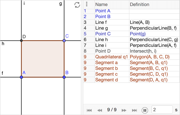
Construct a rectangle yourself! When your done, you can hide the lines. Drag the three movable points, however you move them the polygon should always be a rectangle.
Free and dependent objects
When you make a construction you always have objects that depend on other objects. There is a difference between free and dependent objects.
Try out creating following objects:
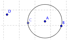
- Make a circle
 using points A and B.
 - Make a point C on the circle.
- Make a point D not on the circle.
- Move all points
You can move the point D freely. If you move A or B you change the circle, these points define the circle. The points A and B are free but the circle is a dependent object, it depends on the points.
If you move C it moves along the circle. C is defined to be a point on the circle and is hence dependent.
Observe the algebra view and choose Sort by: Dependency; the point C and the circle c are dependent objects.
Intersection points
An intersection point is a dependent object that depends on the two objects it intersects. Unlike a point on a circle, an intersection point cannot be moved at all and it is by default colored black. When making constructions keep an eye out on the color of the points. If an intended intersection point isn't black, you have failed intersecting two objects.
In most cases you can use the tool ![]() Point when making an intersection point. Sometimes, however, you want an intersection point where several objects intersect. In that case it may be easier to use the tool
Point when making an intersection point. Sometimes, however, you want an intersection point where several objects intersect. In that case it may be easier to use the tool ![]() Intersect.
Intersect.
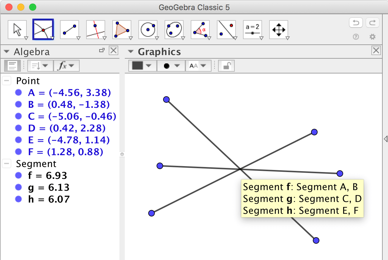
If you, as in the picture, have three segments intersecting at approximately
the same point, don't click on the intersection of the segments but click twice, first on one segments
and then on the other using the Intersect
![]() tool.
You can click on the segments either in the graphics view or the algebra view.
tool.
You can click on the segments either in the graphics view or the algebra view.
Ruler and compass
A geometric construction is often understood as a construction made using only a ruler and compass. Here we use the word construction as a construction you can make using all GeoGebra tools.
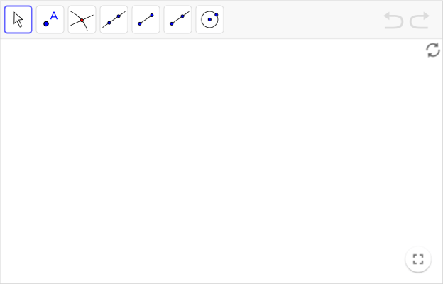
It is possible to use GeoGebra for classical ruler-and-compass-constructions. Choose Tools - > Customize toolbar to pick out the tools corresponding to a classical ruler and compass.
For exercises using a ruler and compass see Geometry ‐ Ruler and Compass or Geometry ‐ Circumscribed and Inscribed Circles.
Exercises
Exercise 1
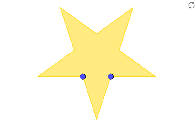
Construct a pentagram
- Make a pentagon (a regular polygon with five sides).
- Make segments between vertices of the pentagon by using the tool
 Segment.
 - If you want to color an area you must turn it into a polygon. The intersection points of the segments must be used as the vertices of the new polygon. Create the five intersection points!
- Use the tool
 Polygon
to create the pentagram.
Polygon
to create the pentagram. - Hide the original pentagon by right-clicking on it and uncheck
Show Object. Also hide segments that you don't want to show. Note that you can not delete the pentagon, it is used in the construction, you can only hide it.


Now you should be able to move the pentagram and change its size by dragging the points A and B; the dragging should not destroy the pentagram. It is this feature that makes it a construction rather than a drawing.
Exercise 2
Construct another pentagram
Construct a pentagram where the two points that all other objects depend on are placed as in the worksheet below.
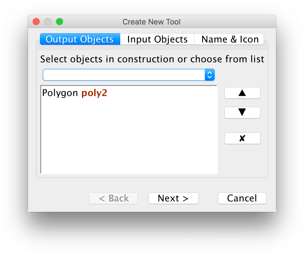
You can make a pentagram-tool under the menu Tools -> Create New Tool.
First select the pentagram as the output object.
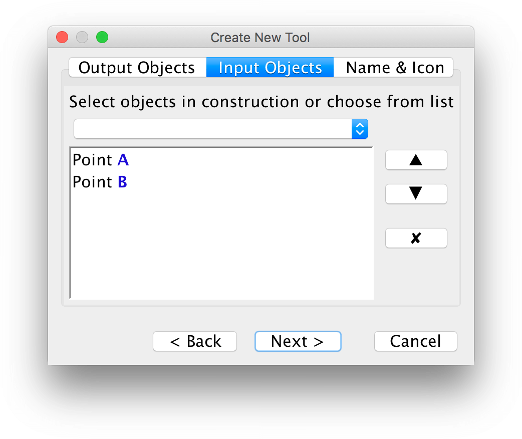
Next select the input objects. In this case they are already selected.
As the last step, give a name to your tool. You can also use an image as the icon for the tool.
Exercise 3
Construct a parallelogram
Make a parallelogram as a construction. When the construction is done, you should be able to move to points to change the size and the appearance; the quadrilateral should still remain a parallelogram when moving the points ‐ it should pass the dragging test.
Exercise 4
Constructions using circles
A circle has the extraordinary property that all points on the circle have the same distance to the midpoint of the circle. Circles are often used in constructions.
- Make an isosceles triangle as a construction. See to it that your construction passes the dragging test.
- Make a rhombus as a construction. See to it that your construction passes the dragging test.
Exercise 5
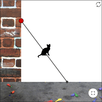
Cat on ladder
Visualize a ladder (between \(A\) and \(B\)) against a wall, a ladder sliding down the wall. On a step on the middle of the ladder (at \(C\)) there is a cat. As the ladder slides down, the cat moves along a circular path.
If you only want the ladder to slide along the positive \(y\)-axis, you place \(A\) on a ray.
Use the tool ![]() Circle with Center and Radius to construct the ladder.
Circle with Center and Radius to construct the ladder.
Use the tool ![]() Midpoint or Center to place the cat.
Midpoint or Center to place the cat.

When you are done you can show the trajectory of the cat by:
- putting a trace on \(C\). You can erase the trace by zooming or moving the graphics view.
- using the tool
 Locus. First click on \(C\) and then on \(A\).
If you want to show an actual cat, you can use the tool ![]() Image to insert images.
Image to insert images.
Exercise 6
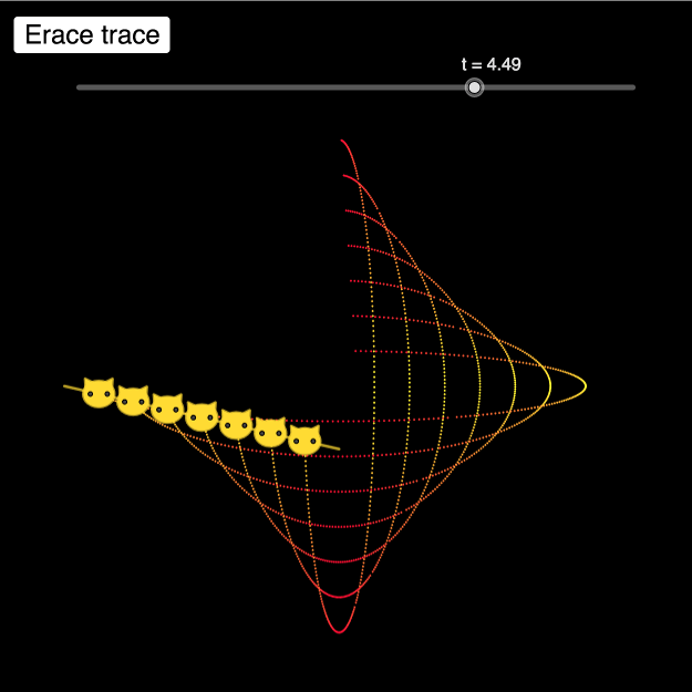
Many cats on a ladder
A cat sitting anywhere on a ladder, will follow an elliptic path when the ladder slides down along a wall.
Construct a ladder as in Exercise 5 and place several cats on the ladder. You can place the cats by using the tool ![]() Midpoint or Center many times.
Midpoint or Center many times.
Instead of making a geometric construction of the ladder, you can use trigonometry and a slider \(t\) representing an angle. How can you express the end points of the ladder in terms of \(t\) in order for the length of the ladder to be constant?
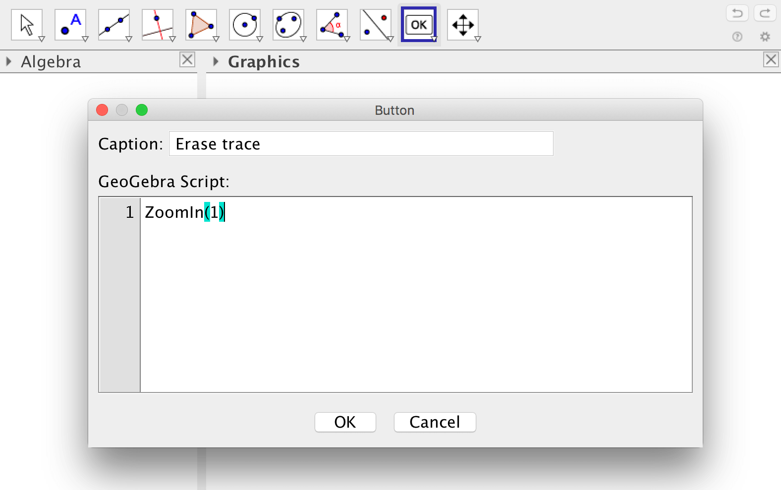
If you want to erase the trace in a more elegant way, you can make a button that zooms using the factor one.
If you want to create many objects it may be easier to use the spreadsheet, see GeoGebra Tutorial - Spreadsheet for more information. On that site it is also shown how to use dynamic colors.
Exercise 7
Peaucellier-Lipkins linkage
The first mechanical linkage that transforms rotary motion into straight-line motion (and vice versa) is the Peaucellier-Lipkin linkage that was invented in 1864.
The linkage can be modelled using GeoGebra, such a model is shown below.
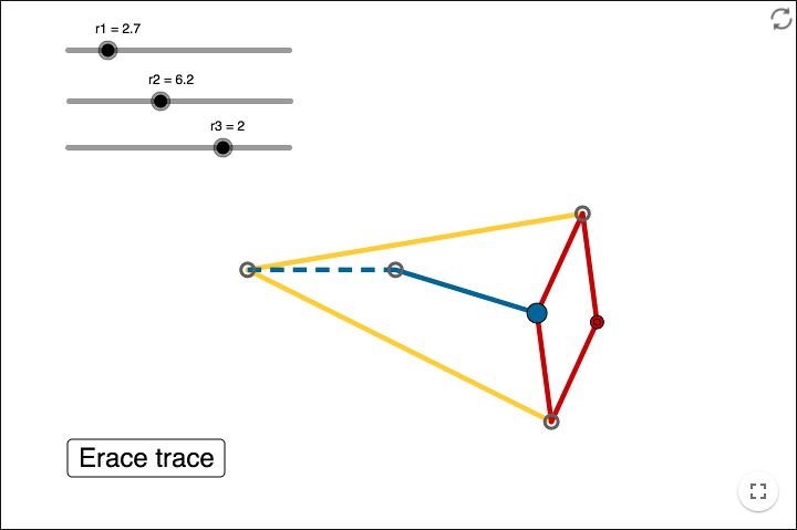
In the figure below some points that are needed are shown. The point \(C\) should be draggable along a circular path. When dragging \(C\) the point \(F\) should move along a line.

There are three distances in the model that should not change when dragging \(C\). Following equalities must hold:
\[ \begin{align*} AB &= AC \\ BD &= BE \\ CD = CE &= DF = EF \end{align*} \]Since these distances should not change, you should use the tool ![]() Circle with Center and Radius. The three radii needed can be represented by sliders.
Circle with Center and Radius. The three radii needed can be represented by sliders.
Make an interactive GeoGebra model of the Peaucellier-Lipkin linkage by following these steps:
Step 1
Construct the three first points, the points called \(A, B, C\) in the figure. The points \(B\) and \(A\) must not move when you drag \(C\).
Step 2
Construct the points called \(D\) and \(E\) in the figure. These two points have the same distance to \(C\) and the same distance to \(B\). How to you make this happen?
Step 3
Construct the point called \(F\) in the figure. How do you do this and still maintain the equalities \(CD = CE = DF = EF\)?
Step 4
When your construction works you can show the rotary path and the straight-line path by letting the corresponding points show a trace. Right-click on a point and check Trace on.
images from:
Cat Silhouette by OCAL from: http://www.clker.com/clipart-11768.html
Bricks by robpatrick from: http://www.flickr.com/photos/alkalinezoo/192889545/
After party by Bright Tal from: http://www.flickr.com/photos/bright/69687519/
other resources:
See this beautiful custom made tool to make a version of Pythagoras' tree, at
Splash scuola ‐ Da Rio Bo a Rio Mandelbrot.
by Malin Christersson under a Creative Commons Attribution-Noncommercial-Share Alike 2.5 Sweden License